In many early military operations, dust was like a hidden "battlefield killer", which brought heavy losses to military equipment. For example, in the North African campaign in the mid-20th century, a large number of military vehicles invaded the engine due to dust, resulting in excessive wear of parts and frequent failure of the power system, which seriously hindered the advancement of combat operations.This series of problems triggered a profound reflection on the dust tolerance of equipment in the military community.
The MIL STD blowing sand and dust test standard has undergone several major revisions. The basic characteristic requirements of dust samples, such as particle size range and mineral composition, have been clarified, making the scientific test a key step forward. With the innovation of wind tunnel technology, the structure and performance standards of blowing sand and dust test chamber have been greatly optimized to more accurately simulate environmental conditions with different wind speeds and dust concentrations. The equipment performance evaluation index system has been further improved, covering the detailed test requirements of equipment in various fields such as machinery, electronics and optics.

The requirements of MIL STD for dust samples are extremely demanding and detailed. From the point of view of physical characteristics, it is stipulated that the particle size of the dust is mainly distributed between 10-500 microns, of which the proportion of the specific particle size interval has a clear limit. This is because dust in this particle size range is most common in natural dust storms and is representative of the erosion effect on equipment. In terms of mineral composition, the sample should contain major minerals such as quartz, feldspar and mica, and their respective content should meet a specific proportion range.
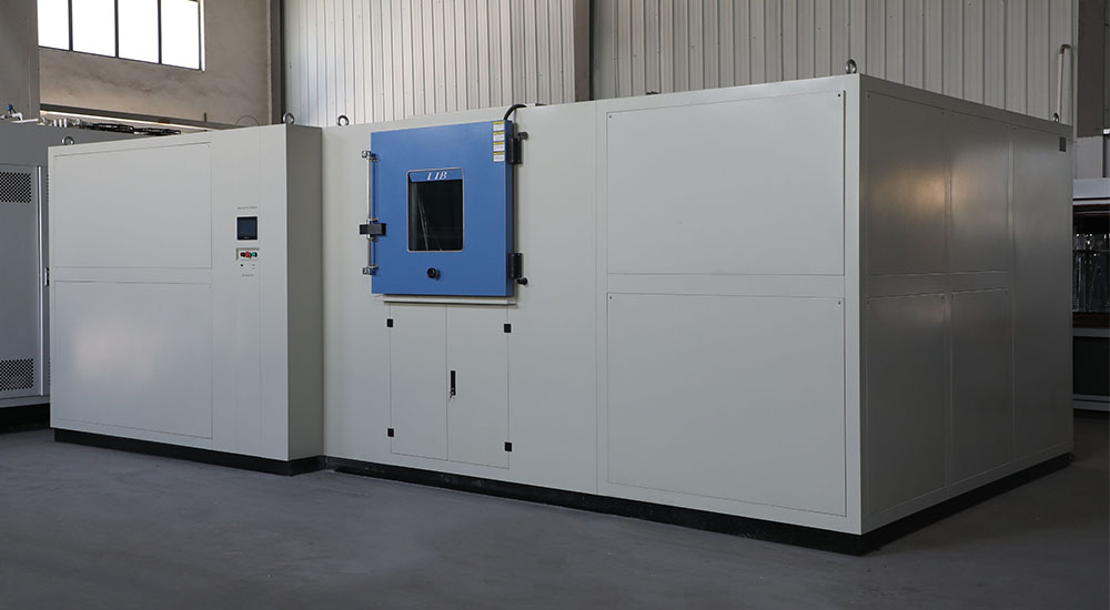
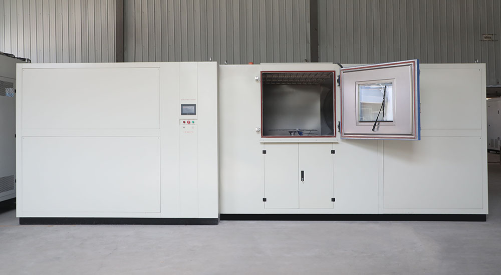
The wind tunnel equipment specifically designed for MIL STD blowing dust testing is a masterpiece of engineering. The air inlet has a special flare design that minimizes airflow resistance and ensures stable and uniform airflow into the wind tunnel. The shape of the air duct is designed as a gradually shrinking and expanding type according to the aerodynamic principle. In the shrinking section, the cross-sectional area is gradually reduced to accelerate the air flow, thus generating high-speed air flow in the test section to meet the test requirements of different dust blowing speeds.

A well-designed dust injection system is installed inside the test section. The dust storage container of the system adopts the structure of anti-blockage and accurate flow control. Driven by high pressure gas, the dust can be sprayed into the air stream at a uniform concentration and stable rate. At the same time, the test section is equipped with advanced wind speed sensors, dust concentration monitors and other monitoring equipment, which can accurately measure key parameters such as wind speed and dust concentration in real time, and transmit the data to the central control system. The central control system adjusts the running state of the wind tunnel equipment in real time according to the preset test parameters to ensure the stability and accuracy of the environmental parameters during the test.
Before testing, blowing dust test chamber to be tested needs to be thoroughly pre-treated. First of all, the equipment is thoroughly cleaned to remove oil, dust and other impurities on the surface to ensure that the test results are not interfered with by other factors. Then, the initial performance of the equipment is tested and recorded in detail. After the equipment pretreatment is completed, the test equipment is strictly debugged and calibrated.
During testing, the equipment is precisely placed in a specific location in the wind tunnel test section. According to the test standard, set the time cycle of dust blowing, which is usually based on the expected use scenario and protection level of the equipment, from a few hours to tens of hours. During the blowing process, the wind speed and dust concentration are adjusted in accordance with the predetermined change mode, for example, to simulate the onset, development, climax and extinction stages of the dust storm, so that the equipment can experience the test of different intensity sand and dust environments.
At the same time, during the test process, the sensor installed on the equipment and the monitoring instrument of the test equipment are used to monitor the performance of the equipment in real time, including the vibration amplitude and temperature changes of the mechanical equipment, the signal transmission stability and power consumption changes of the electronic equipment, and the imaging clarity and light transmittance changes of the optical equipment.
After the test, the equipment is carefully cleaned first. Use special cleaning tools and methods, such as high-pressure air purging, ultrasonic cleaning, etc., to remove the sand residue on the surface and inside of the equipment.
For mechanical equipment, MIL STD focuses on the degree of wear of components. By accurately measuring the quality loss and size change of the parts before and after the test, such as the diameter wear of the shaft parts, the tooth thickness wear of the gear, etc., and comparing with the allowable range specified in the standard, the degree of wear is assessed whether it exceeds the standard. At the same time, the change of structural strength is evaluated, and mechanical testing methods such as tensile, compression and bending are used to detect whether the ability of the equipment to withstand external forces in the sand and dust environment is reduced.

For electronic equipment, the stability of electrical parameters is one of the key evaluation indexes. Monitor the variation range of resistance, capacitance and inductance values, as well as the fluctuation of voltage and current, and determine whether the performance of electronic components is degraded due to dust intrusion. Electromagnetic compatibility is also an important consideration, testing the sensitivity of equipment to external electromagnetic interference in a dusty environment and changes in its own electromagnetic radiation to ensure that it can work properly in a complex electromagnetic environment and does not interfere with other equipment.
For optical equipment, the degree of transmittance reduction is the primary evaluation index. Use a professional spectral photometer to measure the change in the transmittance of an optical lens or lens before and after the test in a specific wavelength range. The resolution test, aberration analysis and other methods were used to evaluate the deterioration of imaging clarity, and the impact of dust on the optical imaging system was checked.